CATIA V5: Creating Electrical Automatic Assembly Between Connectors (Part 1)
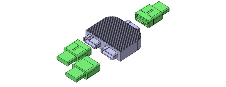
This is the first of a series of posts showing the capabilities of this particular CATIA workbench. The Installation and Equipment workbench can provide ease of installation, robust assembly and routine design reduction by automating the assembly on electrical components. In this post, we will show how to create electrical components and define the rules for the assembly.

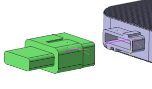
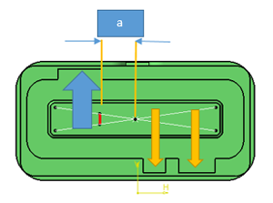
Firstly, the parts should be prepared with some datum features created in Part Design. Those datum’s need to be homogeneous between the parts and must correctly reflect the final assembly positions according to the “key features”. To be clear, when positioned the red and pink lines must match each other.

In order to prevent any errors, dimension “a” needs to be the same for each component and the position of the output line feature in red must be placed in the appropriate orientation.


The following video shows how to set up the model in the Equipment & System workbench in order to allow electrical automatic connection:
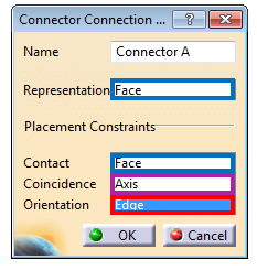
To complete this post, the following illustration recaps the datums and surfaces to use during the Connector Connection Point step.


Want to know more? Read Part 2


