DELMIA V5-6R2015: Create User Representations for Milling
A User Representation will then be attached to the basic tool. The User Representation can contain cutting and non-cutting elements, in a simulation cutting elements will be removing material whilst non-cutting elements will only be referred to by the software for collision detection.
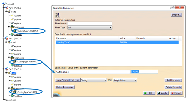
1) The first step is to create a .CATProduct containing the different elements as .CatPart. The different .CATPart have to be identified as cutting or non-cutting elements, to do so a parameter “CuttingType” of type string must be included within the .CATPart. There are 3 types of value accepted for that parameter: HOLDER, SHANK, CUTTER.
The .CATPart without that specific parameter will not be simulated.
2) Next you will need to create the tooling elements themselves. It is important that each element is created on its own profile, and that each profile is created on a sketch.
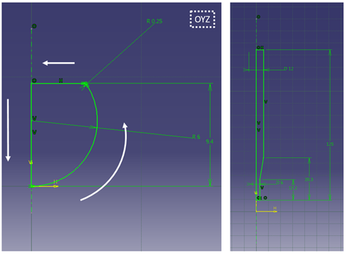
The following points are mandatory to obtain a usable profile:
- Sketch on OYZ plane
- Axis line on the V-axis
- Continuous and closed profile
- Profile starting on the V-axis
- Profile drawn in an anticlockwise direction
- Coordinates on the H-axis have to be positive
- Profiles only composed of cylinders spheres, cones or torus, concave torus
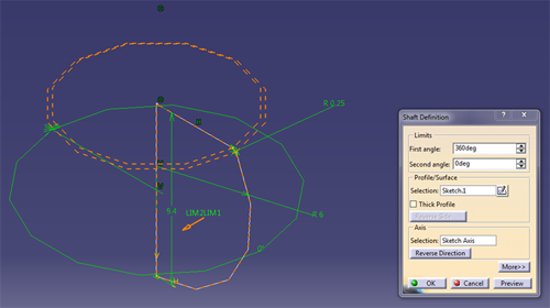
These sketches will then be revolved around the V-axis.
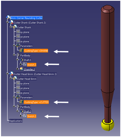
3) Once your tool representation is ready you will have to attach it to the tool used in the manufacturing program.
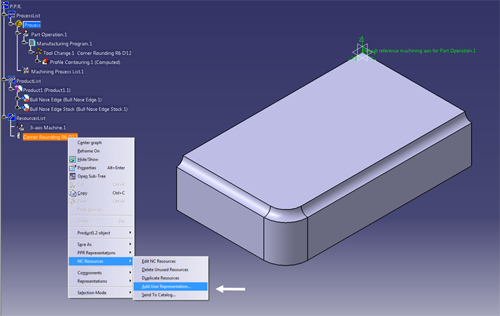
Right click on the tool > NC Resources> Add User Representation. And select the .CATPart or .CATProduct you have just created.
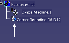
4) Once the User Representation has been added, a blue cog will appear next to the tool in the Resource List:
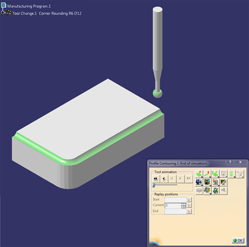
5) The simulation can now be run, it will take in account the User Representation:
For more information, or help with regards to the 3DEXPERIENCE Platform on Premise or on Cloud, please contact our Support.


